In-situ pH Sensor User Manual

Browse online or download User Manual for Accessories for water In-situ pH Sensor. In-Situ pH Sensor User Manual

  • Download
  • Add to my manuals
  • Print
  • Page
    / 5
  • Table of contents
  • BOOKMARKS
  • Rated. / 5. Based on customer reviews
Page view 0
Technical Note
Innovations in
Water Monitoring
Instruction Sheet
Innovations in
Water Monitoring
Page 1 Page 1
Description
The In-Situ® Inc. pH sensor is a combination, single-
junction electrode that contains a replaceable junction
and rellable reference electrolyte solution. The pH
sensor is designed and manufactured for long-lasting,
accurate results in a variety of environmental waters.
Installation
The TROLL 9500 may be shipped with a pH sensor
installed. If installation is necessary, unpack and install
the sensor in port 1 or 3 of the TROLL 9500, Figure 1.
1. Remove the restrictor or Cal Cup from the front
end of the TROLL 9500. This allows access to the
sensor block.
2. Remove the sensor hydration bottle and set aside
for future storage of the sensor.
3. Rinse the sensor with clean water.
4. Remove any moisture or dirt from the area around
the port where you will install the sensor, then use
the sensor removal tool to remove the plug from
the port. Retain the plug for future use.
5. Remove any moisture or dirt from the port
connector with a clean swab or tissue.
6. Remove the cap from the sensor connector. Check
lubrication of the sensor o-rings. If the o-rings
appear dry, apply silicone lubricant, provided in the
sensor box, before installation.
7. Visually align the sensor connector pins with the
port connector pins.
8. Press the sensor firmly into the port until you feel
it dock with the port connector. When properly
inserted, a small gap (the width of the sensor
removal tool) remains between the instrument
body and the widest part of the sensor, for ease
of removal.
Calibration
Although pH may be calibrated with Quick Cal (1
point at pH 7), for best results In-Situ recommends a
2- or 3-point calibration. These options are available in
the software:
• Traditionalcalibration–1point:requires a single
solution; results in calculation of sensor oset for a
single pH value (pH 4, 7, or 10). Select a calibration
solution for the pH range you expect to measure.
• Traditionalcalibration–2point:requires 2
solutions; results in calculation of sensor slope and
oset for one pH range (pH 4-7 or pH 7-10). Choose
solutions for the pH range you expect to measure.
• Traditionalcalibration–3point:requires 3
solutions; results in calculation of slope and oset
for 2 ranges (pH 4-7 and pH 7-10). The correct
slope for the pH values being monitored will
automatically be applied.
• DefaultCoecients: Resets factory defaults to the
sensor. No solutions are required.
Calibration Procedure
pH Sensor
Part Number 0059510
Figure 1. TROLL 9500 pH Sensor Positions
Page view 0
1 2 3 4 5

Summary of Contents

Page 1 - Instruction Sheet

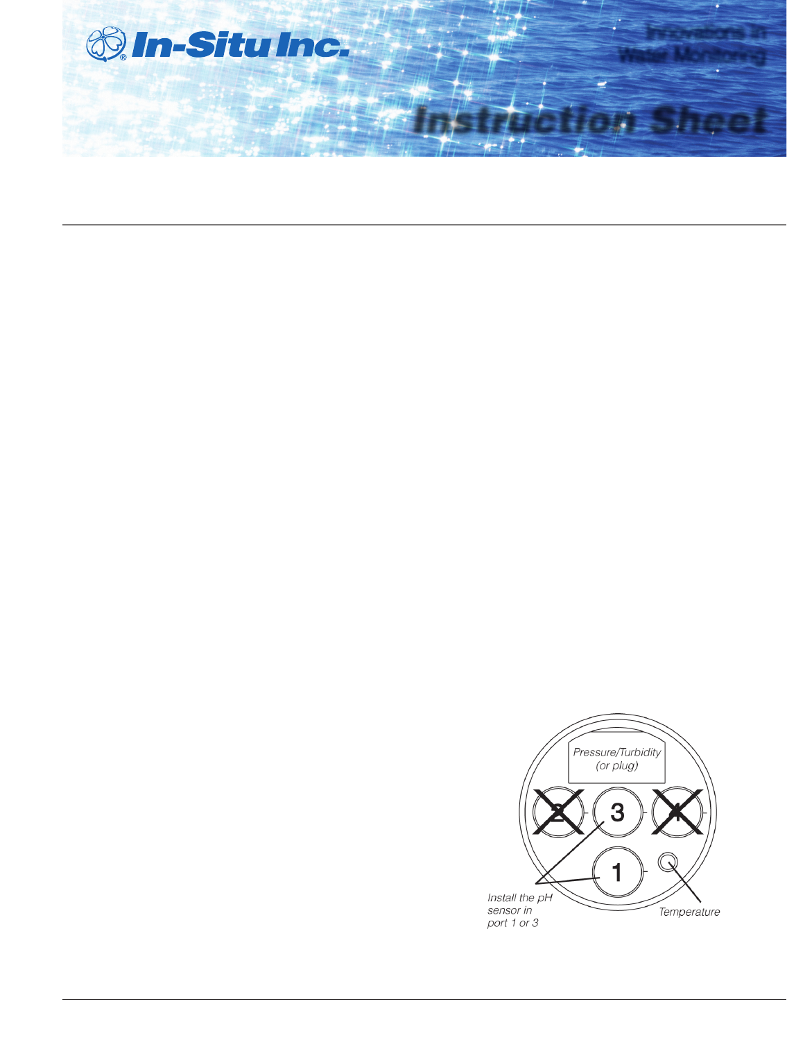
Technical NoteInnovations in Water MonitoringInstruction SheetInnovations in Water Monitoring Page 1 Page 1 DescriptionThe In-Situ® Inc. pH s

Page 2 - Calibration Notes:

Page 2 1. Fill the Cal Cup to the ll line with the selected calibration solution and attach to the instrument.a. With a full set of sensors ins

Page 3 - Sensor Handling and Storage

Page 3 STABLE is displayed when the readings have stabilized. The calibration automatically proceeds to the next screen.• Temperature and baromet

Page 4 - Page 4

Page 4 the dust cap it shipped with, or wrap the sensor in a paper towel to prevent lling solution from entering the electrical connector.4. Hol

Page 5 - Specifications

Page 5 Information subject to change without notice. In-Situ, In-Situ logo, Baro Merge, BaroTROLL, HERMIT, RDO, Pocket-Situ, RuggedCable, RuggedRe

Comments to this Manuals

No comments